Special equipment with deburring function for yoke machining

A special equipment and deburring technology, which is applied in the direction of metal processing equipment, manufacturing tools, metal processing, etc., can solve the problems of inability to clamp the shape of the horn joint, low integration, and weak clamping, etc., to achieve adjustment and Easy and fast effect of positioning

Pending Publication Date: 2022-08-09
重庆明达天晨汽车零部件制造有限公司
View PDF4 Cites 0 Cited by
  • Summary
  • Abstract
  • Description
  • Claims
  • Application Information

AI Technical Summary

Problems solved by technology

[0003] The common problems of the existing yoke processing equipment are: during the production process of the yoke, it is necessary to perform chamfering and deburring processes on the inner hole in the middle of the yoke and the horn holes on both sides. The integration level

Method used


Image

  • Special equipment with deburring function for yoke machining
  • Special equipment with deburring function for yoke machining
  • Special equipment with deburring function for yoke machining

Examples


Embodiment Construction

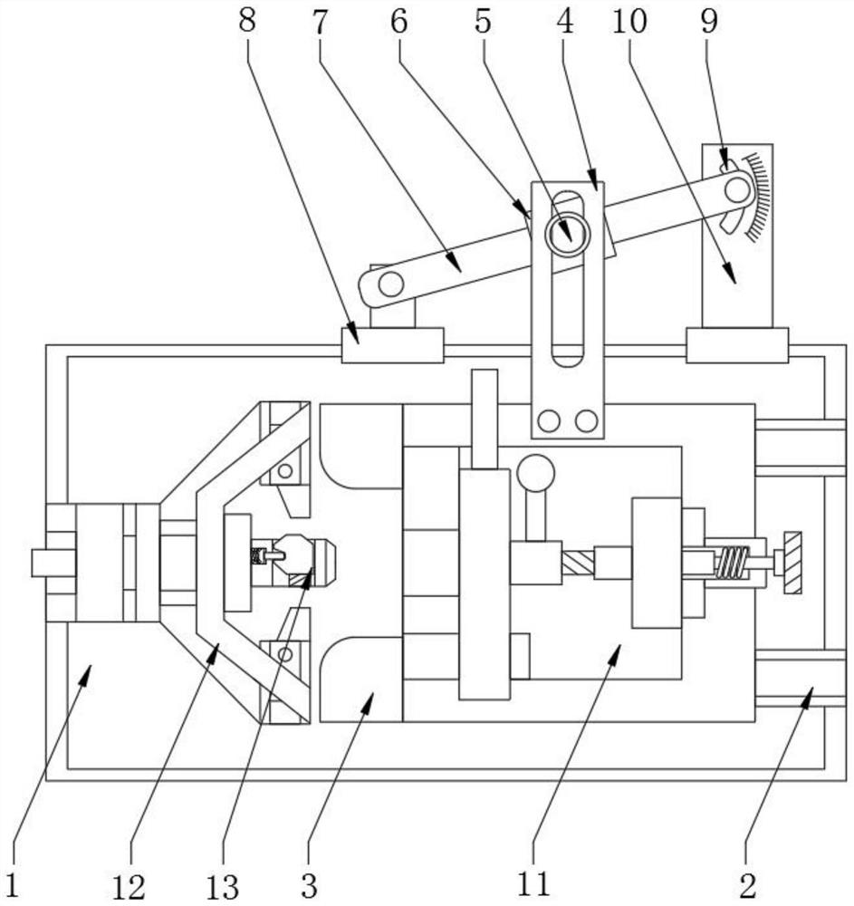
[0027] see figure 1 , The present invention provides a technical solution: a special equipment with deburring for yoke processing, a slide rail 2 is provided on the right side of the top of the bottom plate 1, and a slide table 3 is slidably installed on the top of the slide rail 2, and the top of the slide table 3 is provided with There is a wing plate 4, and a straight groove 5 is formed through the middle of the front of the wing plate 4. The back of the straight groove 5 is rotatably installed with a slider 6, and the base 1101 is connected to the slider 6 through the wing plate 4, and the slider 6 A rocker 7 is provided through sliding inside, the left input end of the rocker 7 is rotated and provided with a left end plate 8, and the right back of the rocker 7 is provided with a scale groove 9, the outside of the scale groove 9 is provided with a right end plate 10, and the left end plate 8 The right end plate 10 is symmetrically and fixedly installed on both sides of the to


PUM


Abstract

The invention discloses special equipment with a deburring function for yoke machining, and relates to the field of yoke machining, the special equipment comprises a bottom plate and a quick clamping mechanism, a sliding rail is arranged on the right side of the top of the bottom plate, and the quick clamping mechanism is longitudinally installed on the top of a sliding table in a sliding mode. The problems that in the production process of a yoke, chamfering and deburring procedures need to be conducted on an inner hole in the middle and claw holes in the two sides of the yoke, two procedures in the prior art need to be executed in a distributed mode, the integration degree between the procedures is not high, and in addition, targeted clamping cannot be conducted according to the shape of the claw joint; in order to solve the technical problems that in the prior art, when a general clamp is used for clamping a special-shaped cleat joint, much inconvenience exists, positioning is inconvenient, and meanwhile clamping is not firm, the invention provides the special device with the deburring function for yoke machining, and the stability of the special device is kept in the machining process through a special clamp specially designed according to the appearance of the cleat joint; and meanwhile, the chamfering process and the deburring process are integrated, one-time positioning is achieved, and operation can be conducted on a plurality of hole positions of the yoke synchronously.

Description


Claims


Application Information

Patent Timeline
Owner 重庆明达天晨汽车零部件制造有限公司
Why Eureka
Try Eureka