Metal-foil laminate and producing method thereof, and method for mounting circuit baseboard by same
A metal foil layer and circuit substrate technology, which is applied in the field of laminates of liquid crystal polymers and metal foils, can solve the problems of difficult use of electrical insulation layer materials, difficulties in thin films, difficulties in manufacturing, etc.
- Summary
- Abstract
- Description
- Claims
- Application Information
AI Technical Summary
Benefits of technology
Problems solved by technology
Method used
Image

Examples
Embodiment 1
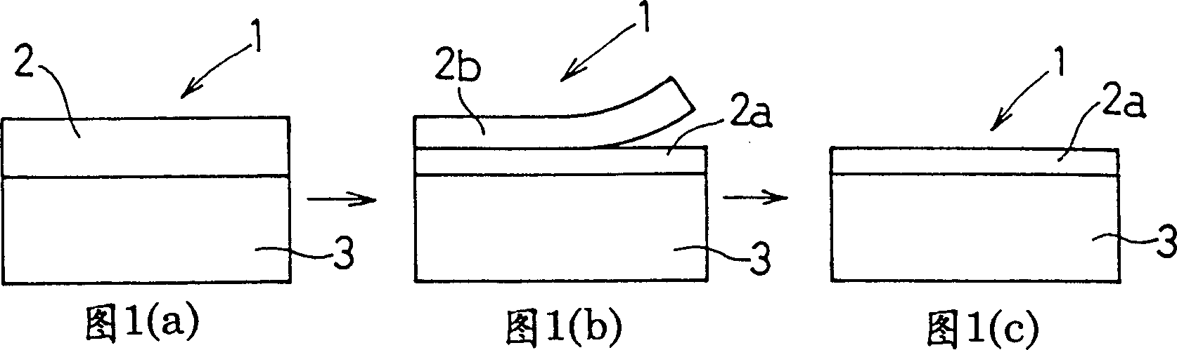
[0080] First, use a single-screw extruder to heat and knead a thermotropic liquid crystal polyester composed of 27 mol% of 6-hydroxy-2-naphthoic acid and 73 mol% of p-hydroxybenzoic acid at 280°C to 300°C. ; They were extruded from an inflatable mold with a diameter of 40 mm and a slit interval of 0.6 mm to obtain a liquid crystal polymer film with a thickness of 75 microns. The resulting liquid crystal polymer film had a melting point of 280°C and a molecular orientation SOR of 1.2. Overlap the aluminum foil (coated body) with a thickness of 200 microns and the liquid crystal polymer film, and use a vacuum flat hot press to draw a vacuum of 40 mmHg from the upper and lower sides; 2 After thermocompression bonding under a certain pressure, the laminate was peeled off, leaving a part of the liquid crystal polymer film.
[0081] Then, the aluminum foil was removed by chemical etching, and the molecular orientation SOR of the obtained liquid crystal polymer coating was determined t
Embodiment 2
[0084] Using a uniaxial extruder, at 280°C to 300°C, heat and knead 27 mol% of 6-hydroxy-2-naphthoic acid and 73 mol% of p-hydroxybenzoic acid to form a thermotropic liquid crystal polyester; They were extruded from an inflatable former with a diameter of 40 mm and a slit spacing of 0.6 mm to obtain liquid crystal polymer films with a thickness of 20 μm. The obtained liquid crystal polymer film had a melting point of 280° C. and a molecular orientation SOR of 1.03.
[0085] With above-mentioned liquid crystal polymer film as the material of liquid crystal polymer coating, overlap with the electrolytic copper foil (coated body) that is 18 microns in thickness, utilize vacuum hot press machine, after the same thermocompression bonding as embodiment 1, After peeling off, a part of the liquid crystal polymer film remains to obtain a liquid crystal polymer coating. The electrolytic copper foil was removed by chemical etching, and the molecular orientation SOR and thickness of the liq
Embodiment 3
[0087]Using a uniaxial extruder, at 280°C to 300°C, heat and knead 27 mol% of 6-hydroxy-2-naphthoic acid and 73 mol% of p-hydroxybenzoic acid to form a thermotropic liquid crystal polyester; They were extruded from an inflatable former with a diameter of 40 mm and a slit spacing of 0.6 mm to obtain liquid crystal polymer films with a thickness of 50 μm. The obtained liquid crystal polymer film had a melting point of 280°C, a molecular orientation SOR of 1.02, and a thermal expansion coefficient of 8 ppm / °C.
[0088] Use the above-mentioned liquid crystal polymer film as the liquid crystal polymer coating material, use a rolled copper foil with a thickness of 10 microns and a thermal expansion coefficient of 18ppm / °C as the material of the coated body, and make the two overlap; then use a vacuum hot press In the same manner as in Example 1, the liquid crystal polymer film was peeled off after thermocompression bonding to leave a part of the liquid crystal polymer film to obtai
PUM
| Property | Measurement | Unit |
|---|---|---|
| Thickness | aaaaa | aaaaa |
| Thickness | aaaaa | aaaaa |
| Thickness | aaaaa | aaaaa |
Abstract
Description
Claims
Application Information
 - R&D Engineer
- R&D Manager
- IP Professional
- Industry Leading Data Capabilities
- Powerful AI technology
- Patent DNA Extraction
Browse by: Latest US Patents, China's latest patents, Technical Efficacy Thesaurus, Application Domain, Technology Topic.
© 2024 PatSnap. All rights reserved.Legal|Privacy policy|Modern Slavery Act Transparency Statement|Sitemap