Apparatus for uniform flow distribution of gas in processing equipment

a technology of processing equipment and apparatus, which is applied in the direction of lighting and heating apparatus, muffle furnaces, furnaces, etc., can solve the problems of insufficient heating or cooling of the entire workpiece, insufficient use of gas at a uniform temperature in order to maintain the same temperature in all areas of the furnace, and increase in furnace operating expenses. , to achieve the effect of simple and economical manufacture and assembly

Active Publication Date: 2006-03-02
SECOWARWICK
View PDF13 Cites 2 Cited by
  • Summary
  • Abstract
  • Description
  • Claims
  • Application Information

AI Technical Summary

Benefits of technology

The present invention provides an improved way to circulate gases during machining processes without affecting their dimensions or materials being transported through it. This results in more efficient production process with less expensive components compared to traditional methods like purgers used upstream from the tool's cutting area.

Problems solved by technology

This patented describes how furnaces have been developed specifically for use with different materials like metal and ceramics during their manufacturing process. However, there may also exist issues where certain parts inside these furnaces get too hot while other parts cool down due to factors like humidity from condensations on surfaces outside them (such as rain). Additionally, when some part of the chamber gets very cold, this causes another issue - even if they were perfectly warmed up beforehand.

Method used


Image

  • Apparatus for uniform flow distribution of gas in processing equipment
  • Apparatus for uniform flow distribution of gas in processing equipment
  • Apparatus for uniform flow distribution of gas in processing equipment

Examples


Embodiment Construction

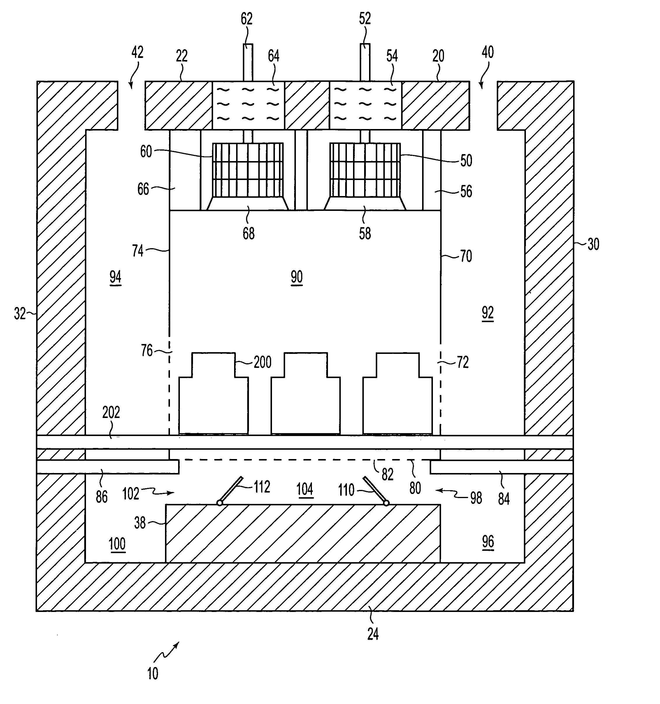
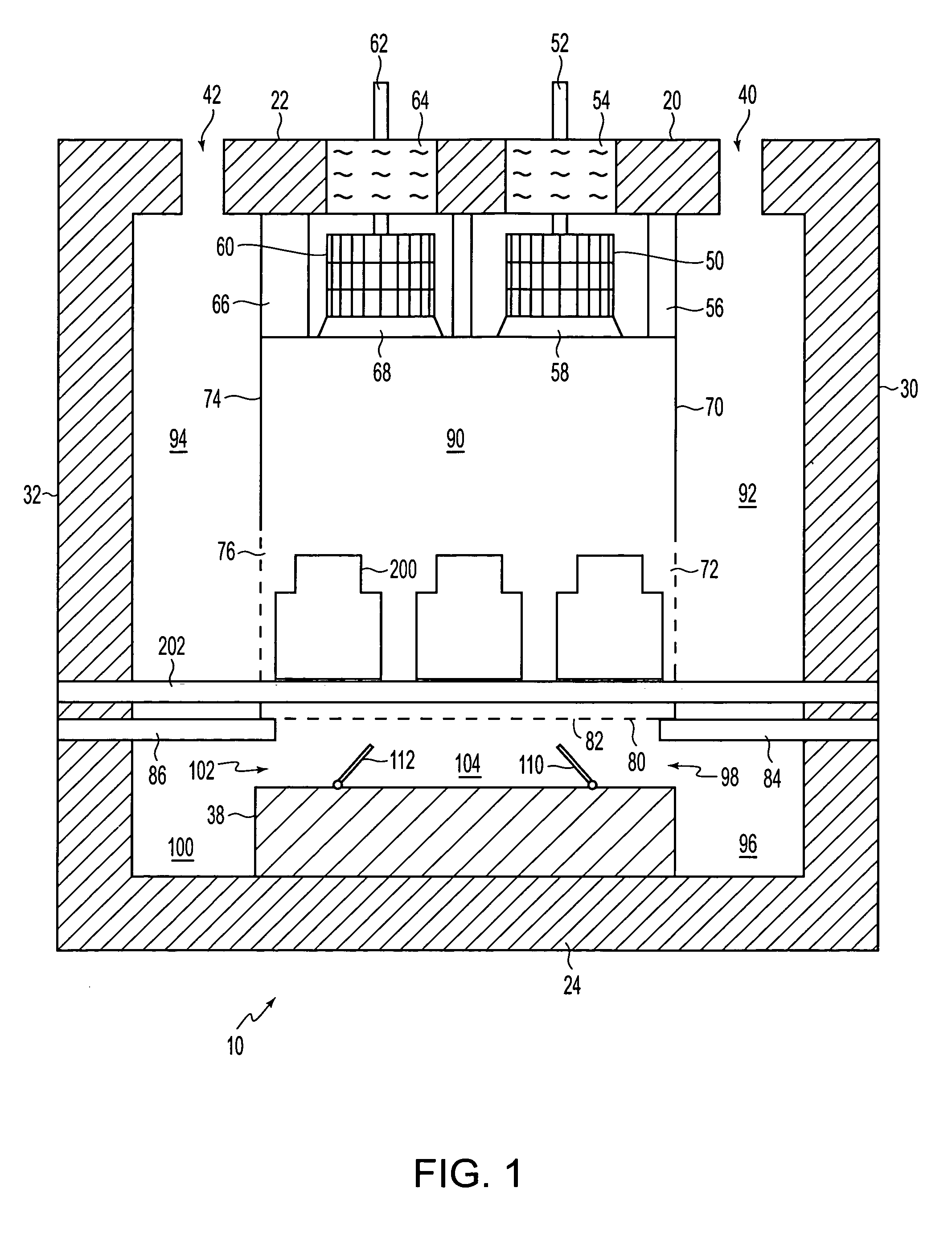
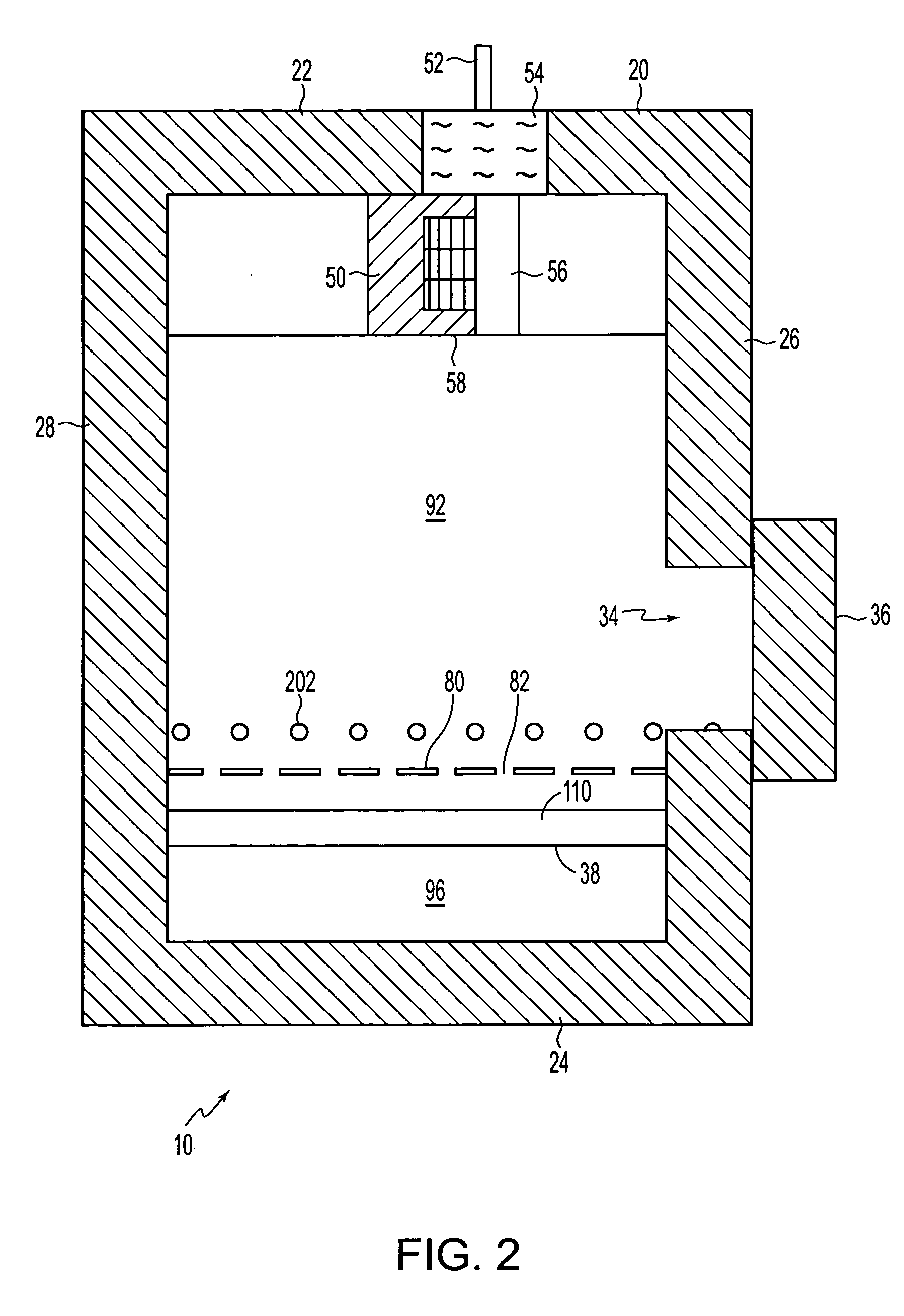
[0024] Referring now in detail to the drawings, there is illustrated in FIGS. 1-3, a furnace as an example of processing equipment. For simplicity and clarification, the operating principles and design factors of the invention are explained with reference to an embodiment of a furnace according to the invention, as shown in FIGS. 1-3. The basic explanation of the operation of the furnace shown in FIGS. 1-3 is applicable for the understanding and design of any processing equipment that incorporates the uniform flow systems and methods according to the invention.

[0025]FIGS. 1-3 show a batch type furnace 10, preferably of metal construction, with a layer of insulating refractory material on the interior to form an insulated enclosure 20. The enclosure 20 has a generally horizontal top wall 22 and bottom wall 24, a generally vertical front wall 26 and rear wall 28, and generally vertical side walls 30, 32. The front wall 26 is formed with a large entrance opening 34 which is adapted to be


PUM


Abstract

A uniform flow control system for processing equipment with a plurality of work pieces located within the processing equipment, including a gas circulating device that circulates gas, a work chamber that can accommodate the plurality of work pieces and an expansion chamber that is located outside the work chamber and that guides gas to the work chamber. The expansion chamber includes a first chamber that extends along a first surface of the work chamber, a second chamber that extends along a second surface of the work chamber to a side of the first chamber, and a third chamber that extends from an end of the first chamber that is opposite the gas circulating device and below an end of the second chamber that is opposite the gas circulating device.

Description


Claims


Application Information

Patent Timeline
Owner SECOWARWICK
Why Eureka
Try Eureka