Atomising nozzle

a technology of atomizing nozzles and nozzles, which is applied in the direction of burners, fuel cells, lighting and heating apparatus, etc., can solve the problems of increasing the cost of production, so as to improve the efficiency and efficiency of vaporization process, improve the operating performance, and improve the effect of vaporization process

Inactive Publication Date: 2006-07-06
ROBERT BOSCH GMBH
View PDF13 Cites 7 Cited by
  • Summary
  • Abstract
  • Description
  • Claims
  • Application Information

AI Technical Summary

Benefits of technology

The present inventor describes an atomizer nozzle system that improves the efficiency of delivering fuel into a specific space while minimizing any negative impacts on the environment. The system uses a special nozzle body made up of a hollow cylindrical tube, allowing for efficient mixing of fuel without adding extra components like fuel cells or reformation processes. Additionally, the system provides a gas supply port located near the top of the nozzle body, where the fuel can be supplied through a pipe connected to a valved manifold. Overall, the system simplifies the production process and reduces costs compared to existing systems.

Problems solved by technology

The technical problem addressed in this patent is how to efficiently convert hydrogen into useful products while minimizing energy consumption and improving the efficiency of the reactor. Existing methods involve cooling the fuel beforehand, but this results in excessive time delays and increases costs. Therefore, the patent proposes a solution involving atomizers that generate mist particles containing fuel molecules, which then enter the reformer through a fine opening called a nozzle. These atomizers help mix the fuel with water vapors, allowing them to evaporate faster and evenly throughout the reformer. Additionally, the patent suggests adding a small amount of fuel to the reformer to ensure complete combustion, thereby increasing the efficiency of the overall process.

Method used


Image

  • Atomising nozzle
  • Atomising nozzle
  • Atomising nozzle

Examples


Embodiment Construction

[0025] In the following, exemplary embodiments of the invention are described by way of example.

[0026] The exemplary embodiments described below of atomizer nozzles designed according to the present invention allow for simple metering and atomization in a hot atmosphere, while providing a robust construction, application in different spatial constellations and the use of standard low-pressure fuel injectors.

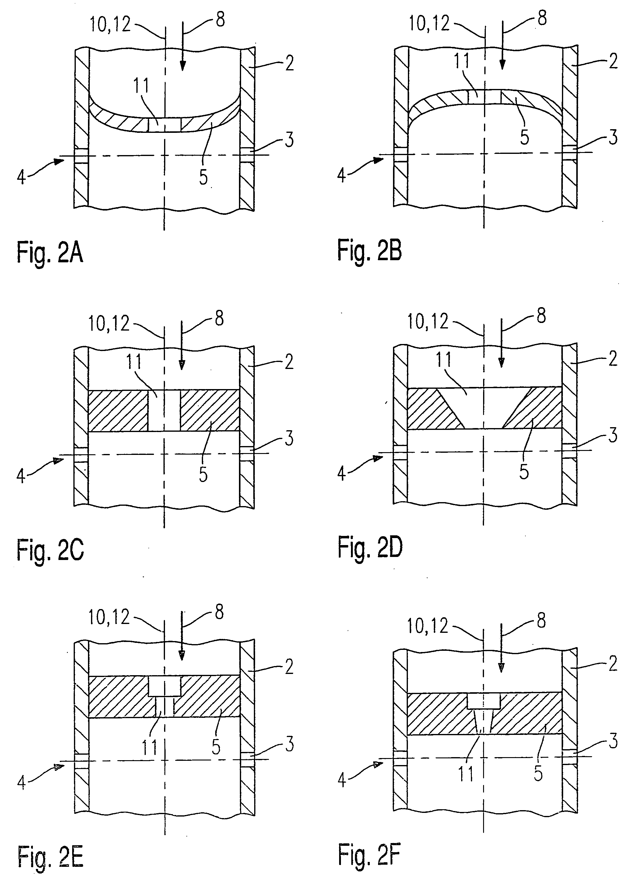
[0027] Identical parts are provided with the same reference numerals in all of the figures. The arrows represent the respective fuel and gas flows.

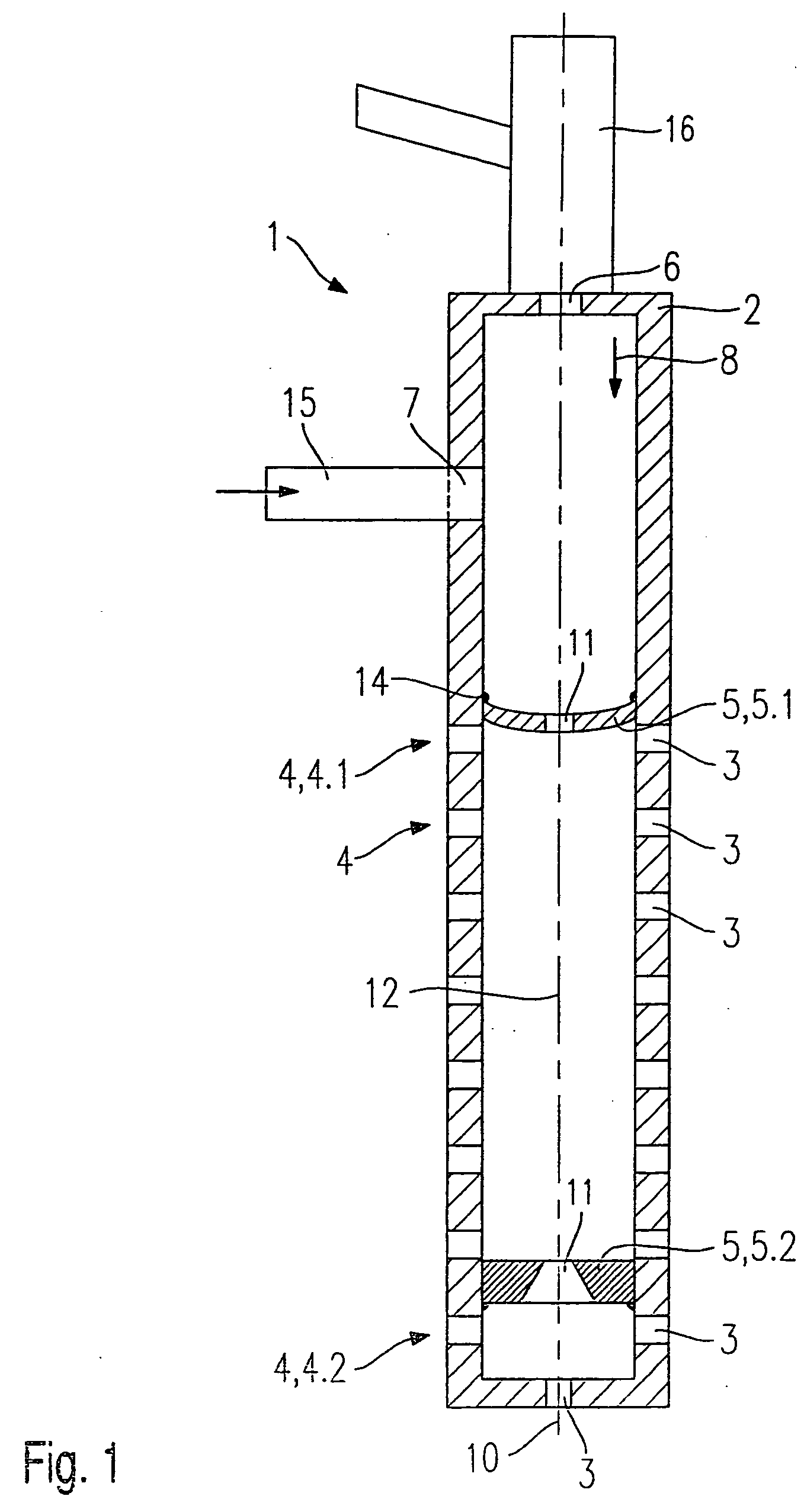
[0028] A first exemplary embodiment, schematically represented in FIG. 1, of an atomizer nozzle 1 according to the present invention is in the form of an atomizer nozzle 1 for the use of low-pressure fuel injectors 16. Atomizer nozzle 1 is particularly suitable for charging and atomizing fuel into a chemical reformer (not shown) for obtaining hydrogen.

[0029] In this exemplary embodiment, atomizer nozzle 1 features a nozzle body 2 in t


PUM


Abstract

An atomizer nozzle for fuels, particularly for charging a chemical reformer for obtaining hydrogen, features a nozzle body, having spray-discharge orifices discharging into a metering space, and at least one metering aperture, The spray-discharge orifices are situated with a radial directional component with respect to a center axis of the nozzle body at elevation levels, each elevation level having at least one spray-discharge orifice. At least one nozzle body insert, having at least one flow-through opening, is situated in the nozzle body in front of the first elevation step in the direction of fuel flow and/or between the elevation steps.

Description


Claims


Application Information

Patent Timeline
Owner ROBERT BOSCH GMBH
Why Eureka
Try Eureka