Unused band use right acquisition controlling method and passive optical network for the same

a technology of acquisition control and passive optical network, applied in data switching network, frequency-division multiplex, instruments, etc., can solve problems such as ineffective us

Inactive Publication Date: 2005-02-01
JUMIPER NETWORKS INC
View PDF10 Cites 28 Cited by
  • Summary
  • Abstract
  • Description
  • Claims
  • Application Information

AI Technical Summary

Benefits of technology

The technical effect of this patented technology allows users to efficiently manage their usage rights without having them pay more money than they are needed or requiring expensive equipment that can be used only on certain bands at once. This helps save time by allowing people who don't want access to these resources while still being able to make it easier if necessary.

Problems solved by technology

This patents describes methods for managing wireless access devices' networks. These techniques involve assigning unique identifiers called addresses into areas where multiple users can communicate simultanously. If one user requests another service call while other users only request their own services, it checks if these IDs match before allowing any new calls. When they meet again, those resources will be reserved for use. However, current systems require manual adjustment of settings and cannot automatically allocate connections among different types of mobile stations efficiently.

Method used


Image

  • Unused band use right acquisition controlling method and passive optical network for the same
  • Unused band use right acquisition controlling method and passive optical network for the same
  • Unused band use right acquisition controlling method and passive optical network for the same

Examples


Embodiment Construction

Hereinafter, an unused band use right acquisition controlling method in a passive optical network (PON) of the present invention will be described with reference to the attached drawings.

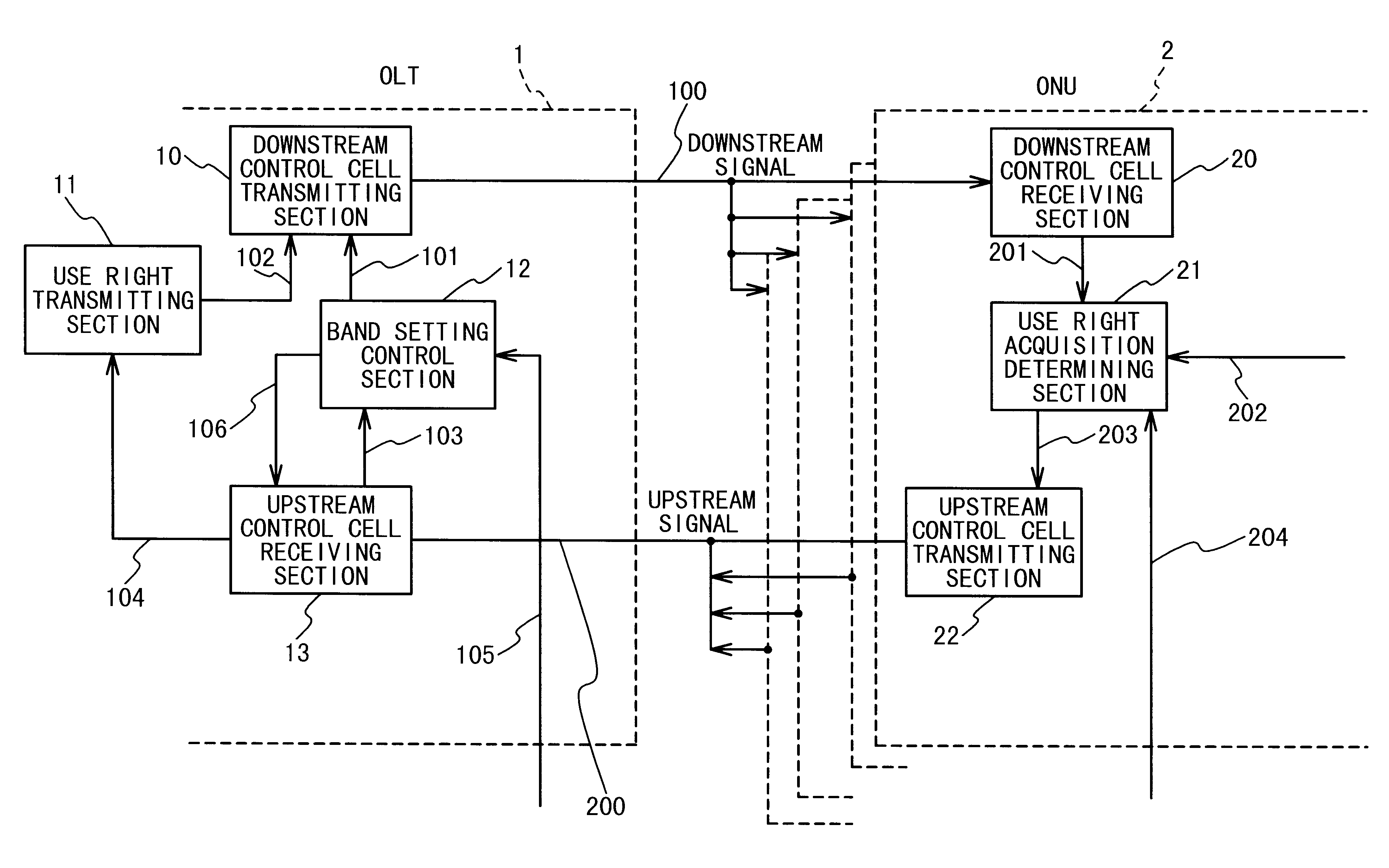
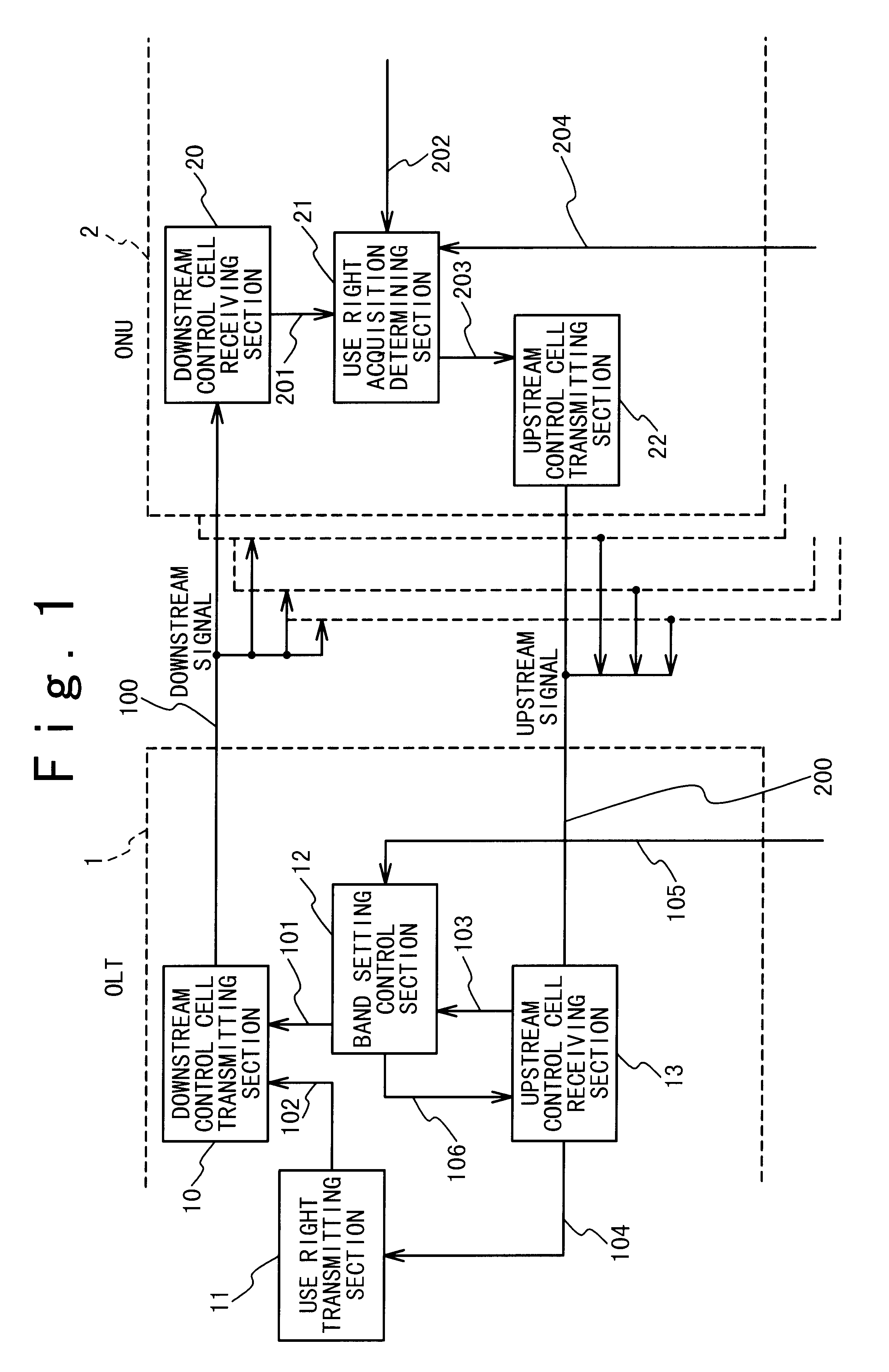
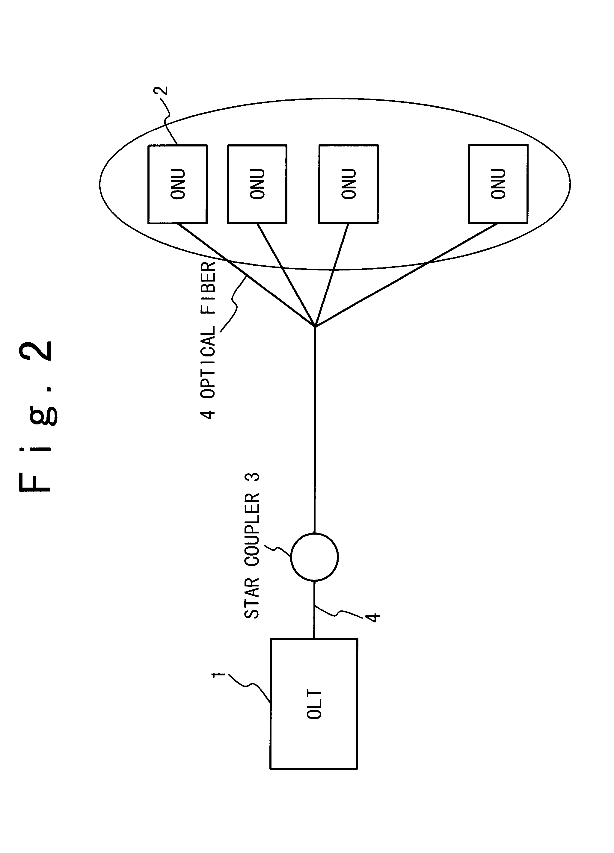
FIG. 1 is a block diagram showing the structure of the passive optical network (PON) in an embodiment. Referring to FIG. 1, the passive optical network (PON) is composed of an optical line termination (OLT) and a plurality of optical network units (ONUs). The unused band use right acquisition controlling method of the present invention is applied to the passive optical network (PON).

The optical line termination (OLT) 1 is composed of a downstream control cell transmitting section 10, a use right transmitting section 11, a band setting control section 12 and upstream control cell receiving section 13.

Also, each of the plurality of optical network units (ONUs) 2 is composed of a downstream control cell receiving section 20, a use right acquisition determining section 21 and an upstream control cell trans


PUM


Abstract

A passive optical network (PON) including an optical line termination (OLT) and a plurality of optical network units (ONUs) which are connected. The optical line termination includes a band setting control section; an upstream control cell receiving section; a use right transmitting section; and a downstream control cell transmitting section. Each of the plurality of optical network units includes a downstream control cell receiving section; a use right acquisition determining section; and an upstream control cell transmitting section.

Description


Claims


Application Information

Patent Timeline
Owner JUMIPER NETWORKS INC
Why Eureka
Try Eureka