Pipeline cutting machine for water conservancy project

A pipe cutting machine and water conservancy engineering technology, applied in the field of water conservancy engineering pipe cutting machines, can solve the problems of single function, limited use, inconvenience of users, etc. of pipe cutting equipment, and achieve the effect of improving convenience and smooth and thorough cutting.

Inactive Publication Date: 2020-04-28
TAIZHOU JIAOJIANG MENFA MASCH TECH CO LTD
View PDF10 Cites 1 Cited by
  • Summary
  • Abstract
  • Description
  • Claims
  • Application Information

AI Technical Summary

Problems solved by technology

[0002] Water conservancy engineering is a project built to control and allocate natural surface water and groundwater to achieve the purpose of eliminating harm and rejuvenating profits. It is also called water engineering

Method used


Image

  • Pipeline cutting machine for water conservancy project
  • Pipeline cutting machine for water conservancy project
  • Pipeline cutting machine for water conservancy project

Examples


Embodiment Construction

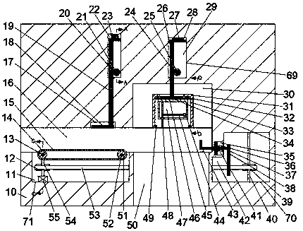
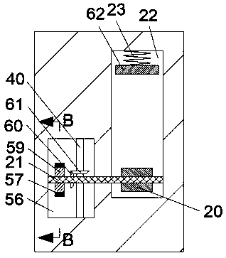
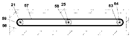
[0016] Combine below Figure 1-5 The present invention is described in detail, and for convenience of description, the orientations mentioned below are now stipulated as follows: figure 1 The up, down, left, right, front and back directions of the projection relationship itself are the same.

[0017] refer to Figure 1-5 According to an embodiment of the present invention, a water conservancy pipe cutting machine includes a casing 10, and the casing 10 is provided with a transport chamber 16 whose left end communicates with the outside world, and the pipe can enter from the left end of the transport chamber 16 for cutting , the casing 10 is provided with a discharge chamber 50 whose lower end communicates with the outside world and whose upper end communicates with the transport chamber 16, the pipe after cutting is discharged through the discharge chamber 50, and the casing 10 is provided with a cutting mechanism 69. The cutting mechanism 69 includes a storage cavity 17 provid


PUM


Abstract

The invention discloses a pipeline cutting machine for water conservancy project. The pipeline cutting machine comprises a machine enclosure, wherein a transportation cavity and a discharging cavity are arranged in the machine enclosure; the left end of the transportation cavity is in communication with the outside world; the lower end of the discharging cavity is in communication with the outsideworld, and the upper end of the discharging cavity is in communication with the transportation cavity; a storage cavity is formed in the machine enclosure; a fixed arc plate is connected to the interior of the storage cavity in a sliding manner, and can move downwards to fix a pipeline; a cutting cavity is formed in the machine enclosure; a fixed block is arranged in the cutting cavity; a fixed block cavity is formed in the fixed block; a cutting block is connected to the interior of the fixed block cavity in a sliding manner; a cutting block cavity and a cutting blade are arranged in the cutting block; the cutting blade rotates to cut the pipeline; a baffle plate is arranged in the transportation cavity; the pipeline is in contact with the baffle plate so as to be controllably cut; a moving transmission mechanism is arranged in the machine enclosure and comprises a driving cavity formed in the machine enclosure; and the lower end wall of the driving cavity is connected to a driving motor which can provide power.

Description


Claims


Application Information

Patent Timeline
Owner TAIZHOU JIAOJIANG MENFA MASCH TECH CO LTD
Why Eureka
Try Eureka