90-degree transmission shaft counter bore machining device

A processing device and transmission shaft technology, applied in positioning devices, metal processing equipment, metal processing mechanical parts, etc., can solve the problems of low processing efficiency and processing, and achieve the effects of high processing efficiency, simple structure and simple operation.

Pending Publication Date: 2020-11-06
南平市建阳区湛卢精密制造有限公司
View PDF0 Cites 0 Cited by
  • Summary
  • Abstract
  • Description
  • Claims
  • Application Information

AI Technical Summary

Problems solved by technology

[0004] The purpose of the present invention is to provide a 90-degree drive shaft countersinking processing device to solve the problem that the countersinking holes of the threade

Method used


Image

  • 90-degree transmission shaft counter bore machining device

Examples


Embodiment Construction

[0014] The following will clearly and completely describe the technical solutions in the embodiments of the present invention with reference to the accompanying drawings in the embodiments of the present invention. Obviously, the described embodiments are only some, not all, embodiments of the present invention. Based on the embodiments of the present invention, all other embodiments obtained by persons of ordinary skill in the art without creative efforts fall within the protection scope of the present invention.

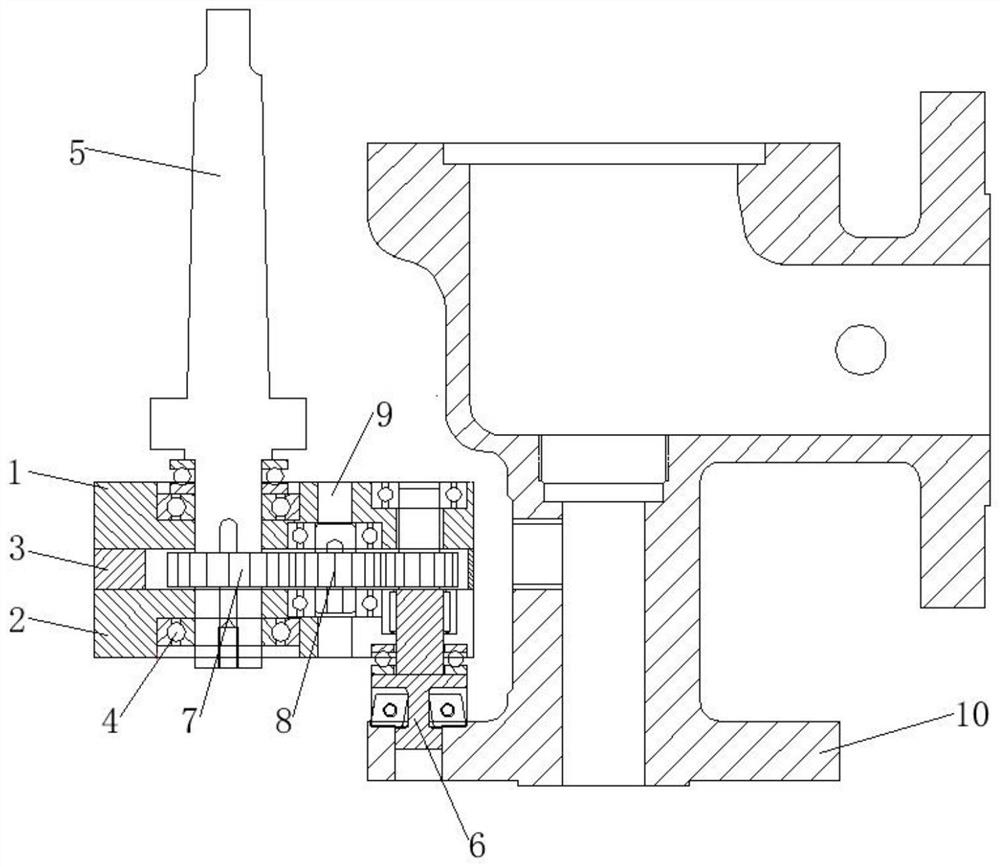
[0015] see figure 1 , the present invention provides a technical solution: a 90-degree drive shaft counterbore processing device, including an upper casing 1 and a lower casing 2, characterized in that a connecting block is installed between the upper casing 1 and the lower casing 2 3. A connecting handle 5 is installed on the left side of the inner cavity of the upper shell 1 and the lower shell 2, and a knife body 6 is installed on the right side of the inner cavity


PUM


Abstract

The invention discloses a 90-degree transmission shaft counter bore machining device. The device comprises an upper shell and a lower shell, wherein a connecting block is installed between the upper shell and the lower shell, a connecting handle is installed on the left sides of inner cavities of the upper shell and the lower shell, a cutter body is installed on the right sides of the inner cavities of the upper shell and the lower shell, first gears are installed on the outer side walls of the connecting handle and the cutter body, and the first gears are arranged in an inner cavity of a notch spaced between the upper shell and the lower shell, second gears are arranged on the sides, close to each other, of the two group of first gears in a meshed mode, and rotating shafts are installed in inner cavities of the second gears. The invention provides the 90-degree transmission shaft counter bore machining device high in machining efficiency.

Description


Claims


Application Information

Patent Timeline
Owner 南平市建阳区湛卢精密制造有限公司
Why Eureka
Try Eureka