Corner grinding machine for tempered glass production based on rotary adjustment
A tempered glass, rotary technology, used in machine tools, grinding frames, and grinders suitable for grinding the edge of workpieces, can solve problems such as increasing labor intensity of workers, and achieve easy glass breaking, increase friction, and reduce labor. the effect of strength
- Summary
- Abstract
- Description
- Claims
- Application Information
AI Technical Summary
Problems solved by technology
Method used
Image

Examples
Embodiment 1
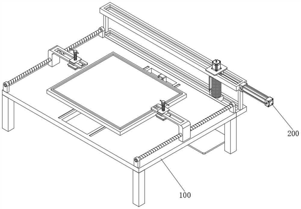
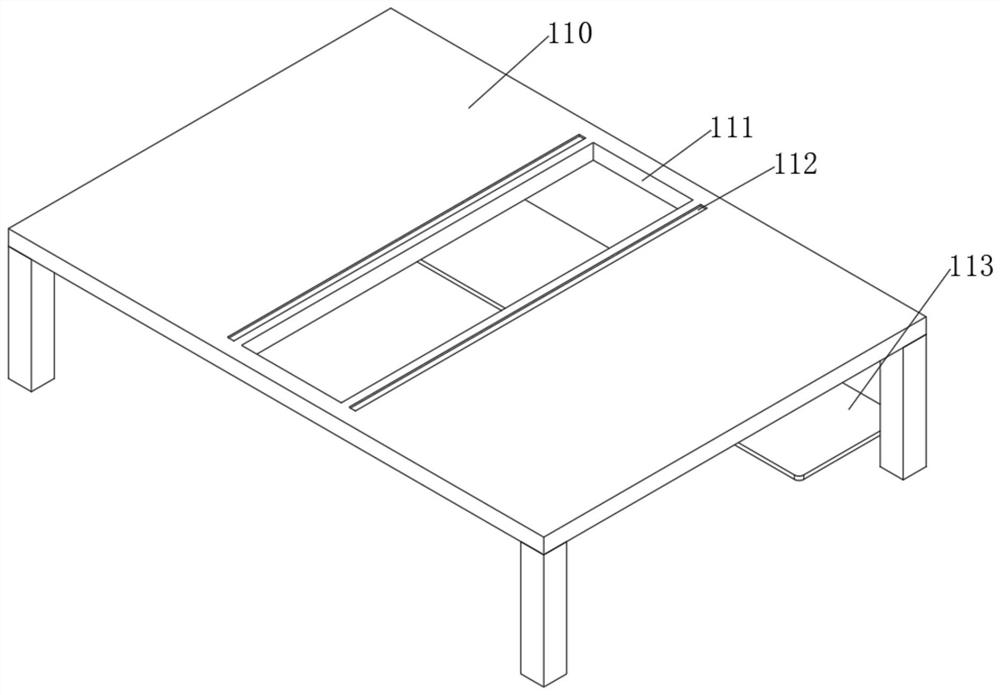
[0049] see Figure 1-Figure 9As shown, an edge grinder for tempered glass production based on rotary adjustment is provided, including an installation device 100 and a grinding device 200 installed on the installation device 100, the installation device 100 includes an installation table 110, and the surface of the installation table 110 is provided with Grooving 111, grinding device 200 at least includes:
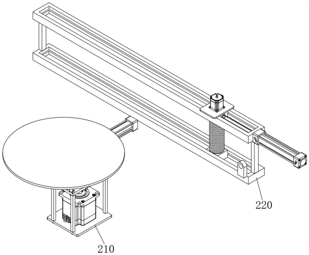
[0050] An adjustment mechanism 210, the adjustment mechanism 210 includes a first telescopic rod 211, one end of the first telescopic rod 211 is fixed on one side of the slot 111, the movable end of the first telescopic rod 211 is fixedly connected with a mounting block 212, and the mounting block 212 is a working Glyph structure, the installation block 212 is slidingly connected with the slot 111, the surface of the installation block 212 is provided with a round hole, and the support platform 213 is connected to the rotation in the round hole, and the bottom outer wall of t
Embodiment 2
[0057] In order to realize fixing to glass, carry out following improvement on the basis of embodiment 1:
[0058] see Figure 10 As shown, wherein, the two ends of the surface of the mounting table 110 are fixedly connected with a fixed plate 120, the fixed plate 120 is in an "L" shape structure, one end of the fixed plate 120 is threaded with a threaded column 121, and one end of the threaded column 121 is rotatably connected with a pressure plate 122, by twisting the threaded column 121, the threaded column 121 drives the pressure plate 122 to move down to fix the glass. At the same time, the pressure plate 122 is preferably made of rubber, and the rubber has strong flexibility, so as to prevent the threaded column 121 from crushing the glass .
[0059] In addition, in order to fix different glasses, the outer wall of one end of the fixing plate 120 is provided with a chute 123, and a first slider 124 is slidably connected in the chute 123, and the first slider 124 is threade
Embodiment 3
[0062] In order to facilitate the collection of burrs produced during grinding, the following improvements are made on the basis of Example 1:
[0063] see Figure 11-Figure 12 As shown, wherein, the bottom of the mounting table 110 is fixedly connected with a bearing plate 113, the surface of the bearing plate 113 is equipped with a collection box 130, and a negative pressure machine 131 is arranged in the collection box 130, and the inner walls on both sides of the collection box 130 are fixedly connected. There is a filter plate 132, one side of the collection box 130 is communicated with an air duct 133, the other end of the air duct 133 is fixed on one side of the second slider 223, and the top of the collection box 130 is connected with a top cover 134. The negative pressure machine 131 is powered, and the negative pressure machine 131 works to generate negative pressure, and the negative pressure sucks the burrs polished at the grinding roller 224 into the collection box 1
PUM
 Abstract
Description
Claims
Application Information
 - R&D Engineer
- R&D Manager
- IP Professional
- Industry Leading Data Capabilities
- Powerful AI technology
- Patent DNA Extraction
Browse by: Latest US Patents, China's latest patents, Technical Efficacy Thesaurus, Application Domain, Technology Topic.
© 2024 PatSnap. All rights reserved.Legal|Privacy policy|Modern Slavery Act Transparency Statement|Sitemap