Conductive paste composite
a technology of conductive paste and composite materials, applied in the direction of non-metal conductors, conductors, metal/alloy conductors, etc., can solve the problems of low productivity, incomplete combustion, bubbles, cracks, etc., and achieve the effect of simple process
- Summary
- Abstract
- Description
- Claims
- Application Information
AI Technical Summary
Benefits of technology
Problems solved by technology
Method used
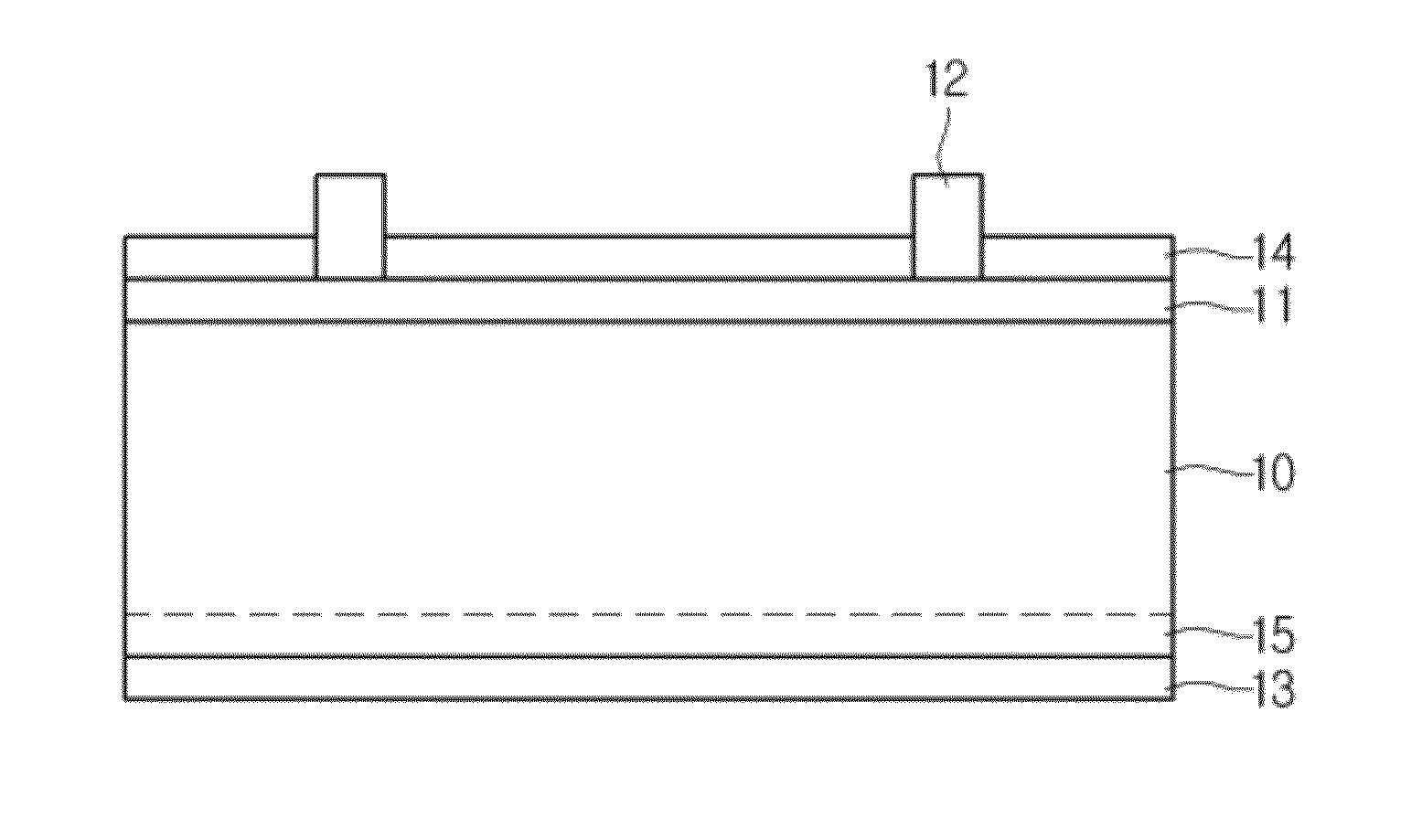
Image

Examples
example 1
[0046]A binder was solved in a solvent to prepare an organic vehicle. A blend of diethylene glycol monobutyl ether acetate and α-terpineol was used as the solvent, and a binder illustrating ethyl cellulose was used as the binder. Silver powder and glass frit were added to the organic vehicle and were mixed. The mixture was aged for 12 hours and secondarily mixed and dispersed using a three-roll mill. Then, the mixture was prepared as a paste composite through filtering and defoaming processes.
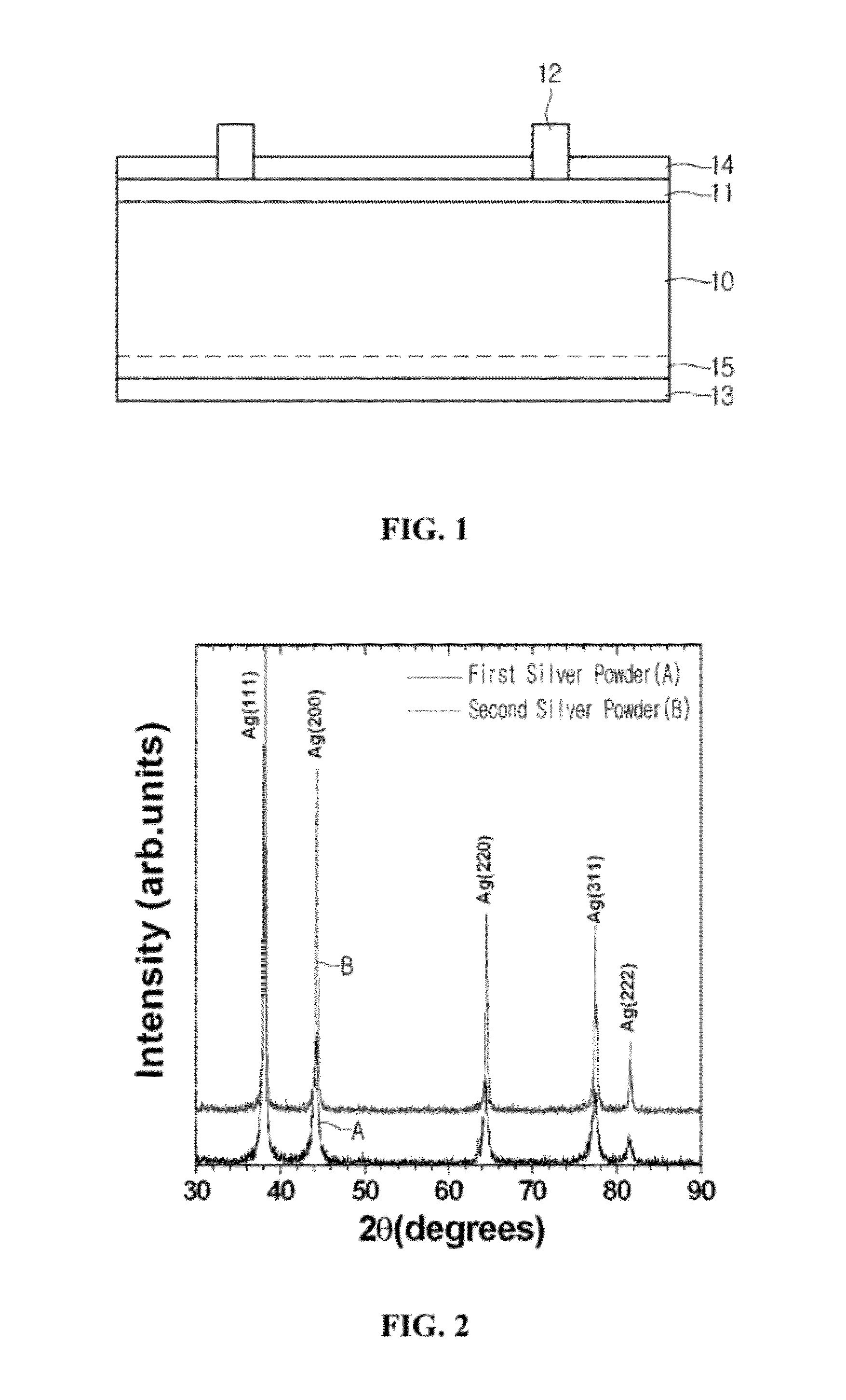
[0047]The paste composite included 15 wt % of the organic vehicle, 80 wt % of the silver powder, and 5 wt % of the glass frit. The silver powder included: 90 wt % of first silver powder having a grain size in the range from 25 nm to 35 nm; and 10 wt % of second silver powder having a grain size in the range from 65 nm to 75 nm. FIG. 2 shows results of x-ray diffraction analysis performed on the first silver powder and the second silver powder.
[0048]The paste composite was applied to a substrate by
example 2
[0049]Eight electrode samples were made in the same manner as that of Example 1 except for silver powder included 80 wt % of first silver powder and 20 wt % of second silver powder.
example 3
[0050]Eight electrode samples were made in the same manner as that of Example 1 except for silver powder included 70 wt % of first silver powder and 30 wt % of second silver powder.
PUM
| Property | Measurement | Unit |
|---|---|---|
| Grain size | aaaaa | aaaaa |
| Grain size | aaaaa | aaaaa |
| Grain size | aaaaa | aaaaa |
Abstract
Description
Claims
Application Information
 - R&D Engineer
- R&D Manager
- IP Professional
- Industry Leading Data Capabilities
- Powerful AI technology
- Patent DNA Extraction
Browse by: Latest US Patents, China's latest patents, Technical Efficacy Thesaurus, Application Domain, Technology Topic.
© 2024 PatSnap. All rights reserved.Legal|Privacy policy|Modern Slavery Act Transparency Statement|Sitemap