Sintered bearing and manufacturing method for same
- Summary
- Abstract
- Description
- Claims
- Application Information
AI Technical Summary
Benefits of technology
Problems solved by technology
Method used
Image
Examples
first embodiment
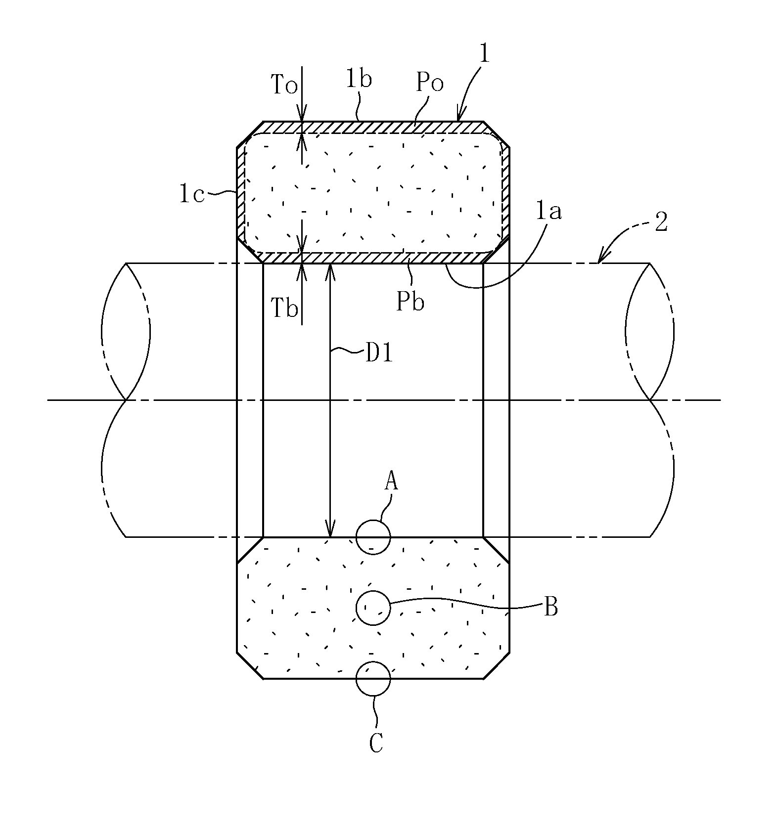
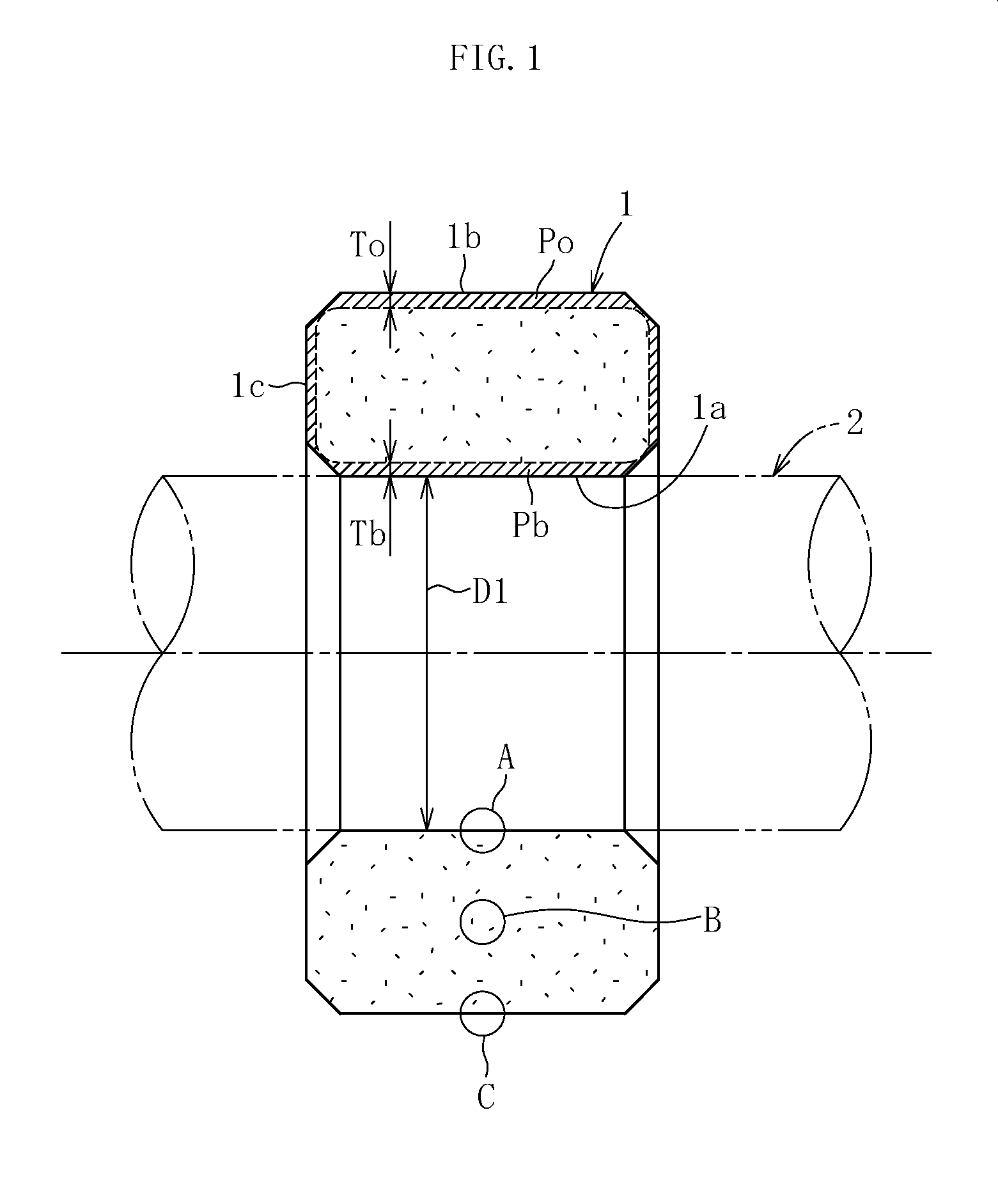
[0048]As illustrated in FIG. 1, a sintered bearing 1 as the sintered bearing is formed in a cylindrical shape having a bearing surface 1a on an inner circumference. When a shaft 2 is inserted with respect to the inner circumference of the sintered bearing 1, and the shaft 2 is rotated in this state, lubricating oil held in an indefinite number of pores of the sintered bearing 1 seeps out from the bearing surface 1a along with an increase in temperature. The lubricating oil that has seeped out forms an oil film between a bearing gap between the outer circumferential surface of the shaft 2 and the bearing surface 1a, and the shaft 2 is supported by the bearing 1 so as to be rotatable relatively.
[0049]The sintered bearing 1 according to the first embodiment is formed by filling a form with raw material powder obtained by mixing various powders, compressing the raw material powder to form a green compact, and then sintering the green compact.
[0050]The raw material powder is mixed powder c
second embodiment
[0096]In the second embodiment, copper powder, aluminum-copper alloy powder, and phosphorus alloy powder are mixed at such a ratio that the content of aluminum is from 7 to 12% by mass, the content of phosphorus is from 0.05 to 0.5% by mass, and the balance comprises copper as a main component, and a total of 0.05 to 0.2% by mass of aluminum fluoride and calcium fluoride serving as the sintering aid and 1 to 5% by mass of graphite are mixed with a total of 100% by mass of the above-mentioned mixture to obtain raw material powder.
[0097][Aluminum Fluoride and Calcium Fluoride]
[0098]An aluminum oxide film to be generated on a surface of aluminum-containing copper-based alloy powder during sintering inhibits the sintering remarkably. However, aluminum fluoride and calcium fluoride serving as the sintering aid evaporate gradually while being melted at a sintering temperature of from 850 to 900° C. of the aluminum-containing copper-based alloy powder and protect the surface of the aluminum-c
third embodiment
[0112]FIG. 9 illustrates an example of a fuel pump for an automobile engine mounted with the sintered bearing incorporated therein. In a fuel pump 40, the sintered bearing 1 is provided on the rotation side. Specifically, the fuel pump 40 includes a casing 41 having a liquid inlet 41a and a liquid outlet 41b, a fixed shaft 2 fixed to the casing 41 and protruding to an internal space of the casing 41, an impeller 42 provided rotatably with respect to the fixed shaft 2, a motor 43, a magnet 44 mounted on the impeller 42, and a magnet 45 mounted on a rotation shaft of the motor 43 and opposing in a radial direction to the magnet 44 on the impeller 42 side. The sintered bearing 1 is fixed to an inner circumferential surface of the impeller 42, and an inner circumferential surface (bearing surface 1a, see FIG. 1) of the sintered bearing 1 and an outer circumferential surface of the fixed shaft 2 are fitted to each other slidably in a rotation direction. When the motor 43 is driven to rotat
PUM
| Property | Measurement | Unit |
|---|---|---|
| Temperature | aaaaa | aaaaa |
| Percent by mass | aaaaa | aaaaa |
| Percent by mass | aaaaa | aaaaa |
Abstract
Description
Claims
Application Information
 - R&D Engineer
- R&D Manager
- IP Professional
- Industry Leading Data Capabilities
- Powerful AI technology
- Patent DNA Extraction
Browse by: Latest US Patents, China's latest patents, Technical Efficacy Thesaurus, Application Domain, Technology Topic.
© 2024 PatSnap. All rights reserved.Legal|Privacy policy|Modern Slavery Act Transparency Statement|Sitemap


