Light control-based organic spin memory cell

A storage unit and light regulation technology, applied in information storage, static memory, digital storage information, etc., can solve problems such as increasing the difficulty of device manufacturing and production cost, the rate limit of magnetic field changes, and the large write delay of storage devices, etc. Achieve the effect of reducing power consumption, facilitating production and processing, and improving integration

Active Publication Date: 2016-09-07
BEIHANG UNIV
View PDF6 Cites 4 Cited by
  • Summary
  • Abstract
  • Description
  • Claims
  • Application Information

AI Technical Summary

Problems solved by technology

[0005] 1. During the writing process, a large magnetic field is required to realize the magnetization reversal of the ferromagnetic electrode, and a large magnetic field requires a large external current, which leads to a significant write power consumption of the device
[0006] 2. Due to the hysteresis effect of the ferromagnetic electrodes, the rate o

Method used


Image

  • Light control-based organic spin memory cell
  • Light control-based organic spin memory cell
  • Light control-based organic spin memory cell

Examples


Embodiment Construction

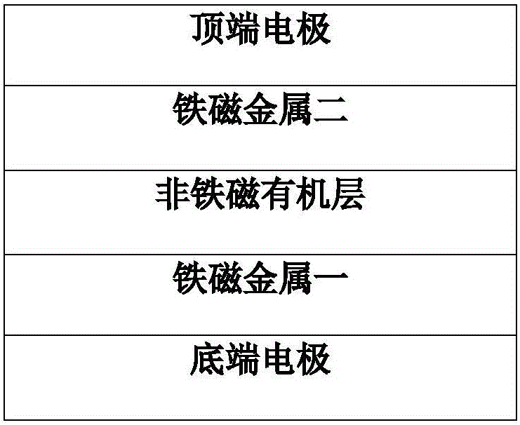
[0042] Referring to the accompanying drawings, the substantive features of an organic spin storage unit based on light regulation of the present invention will be further described.

[0043] The invention proposes an organic spin storage unit based on light regulation, which can be used for both large-capacity magneto-optical storage and optical signal detection, so the storage unit can be used to design the memory hierarchy.

[0044] Detailed exemplary embodiments are disclosed herein, specific structural and functional details thereof are merely representative for purposes of describing exemplary embodiments, therefore, the invention may be embodied in many alternative forms and should not be construed To be limited only to the exemplary embodiments set forth herein, all changes, equivalents, and alternatives falling within the scope of the invention should be covered. Additionally, well-known elements, devices and subcircuits of the invention will not be described in detail or


PUM


Abstract

The invention provides a light control-based organic spin memory cell. A structure of the memory cell comprises the following components from bottom to up in order: a bottom electrode, a ferromagnetic metal layer 1, an organic nonferromagnetic layer, a ferromagnetic metal layer 2, and a top electrode; the bottom electrode comprises one or more of gold, platinum, copper or other nonferromagnetic metal materials; the ferromagnetic metal layer 1 comprises one or more of iron, cobalt, nickel, cobalt-iron-boron, nickel-iron, lanthanum strontium manganese oxide, Heusler alloy or other ferromagnetic materials; the nonferromagnetic layer organic material comprises aluminum tris-(8-hydroxyquinoline) (Alq3), alpha-sexithiophene (6T) or other photosensitive organic materials; the ferromagnetic metal layer 2 comprises one or more of cobalt, cobalt-iron, cobalt-iron-boron, Heusler alloy or other ferromagnetic materials; the top electrode comprises one or more of gold, platinum, copper or other nonferromagnetic metal materials.

Description


Claims


Application Information

Patent Timeline
Owner BEIHANG UNIV
Why Eureka
Try Eureka