Grating external cavity feedback semiconductor laser and adjusting method thereof

An external cavity feedback and semiconductor technology, which is applied in the optical field, can solve the problems of relative movement and semiconductor laser working in a stable state for a long time, and achieve the effects of easy adjustment, stable frequency and increased feedback control band

Active Publication Date: 2019-06-25
北京瓦科光电科技有限公司
View PDF9 Cites 1 Cited by
  • Summary
  • Abstract
  • Description
  • Claims
  • Application Information

AI Technical Summary

Benefits of technology

This patented technology describes an improved version of a type called LC resonance (LCR) optoelectrolled Feher crystal oscillator (LMF). It uses a reflective optical element made from materials like gallium nitride or vanadium oxide instead of traditional gratings. These elements allow for precise movement along one dimension without being affected by gravity forces. Additionally, they provide better performance than previous designs due to their smaller size and longer lifespan. Overall, this new design allows for greater flexibility in manufacture and higher efficiency in operation.

Problems solved by technology

This technical problem addressed in this patented text relates to how optimal the design of gratings affects the performance (stress) of semiconducer devices like those described above during use over longer periods without losing accuracy when they experience changes caused by environmental factors such as temperature fluctuation.

Method used


Image

  • Grating external cavity feedback semiconductor laser and adjusting method thereof
  • Grating external cavity feedback semiconductor laser and adjusting method thereof
  • Grating external cavity feedback semiconductor laser and adjusting method thereof

Examples


Embodiment Construction

[0047] In order to further illustrate the technical solution of the present invention, the present invention will be further described below in conjunction with the accompanying drawings and embodiments.

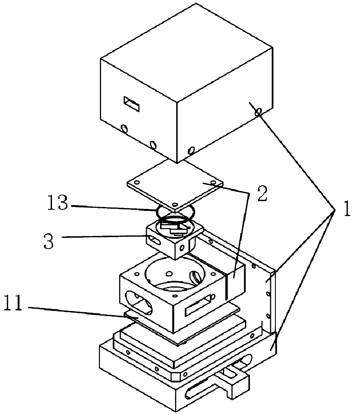
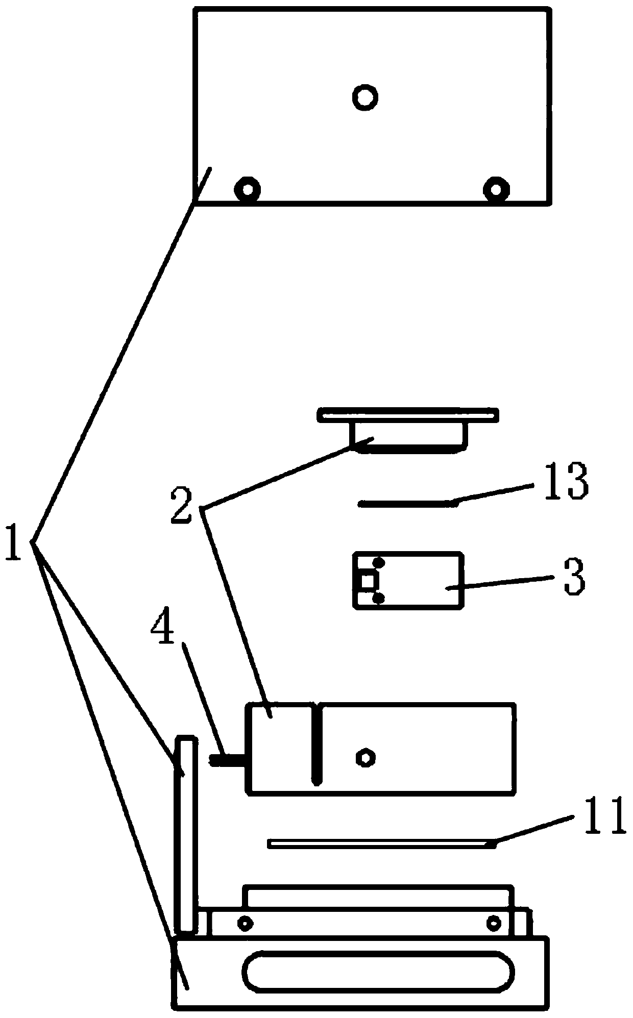
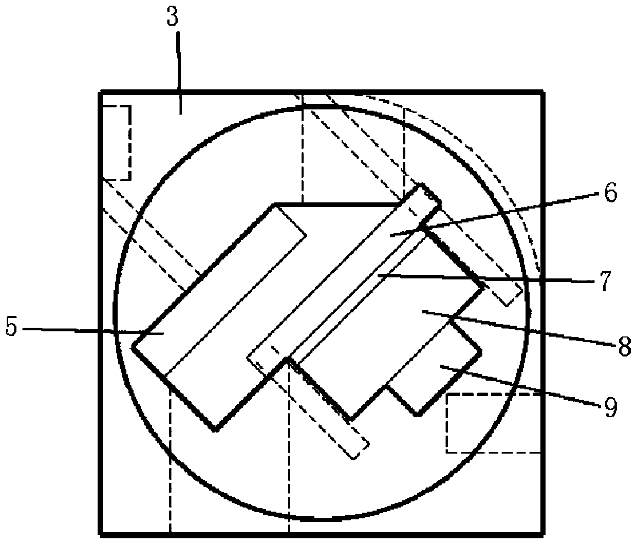
[0048] Such as Figure 1 to Figure 14 As shown, a grating external cavity feedback semiconductor laser includes a housing 1, a substrate 2, a grating frame 3, a laser diode 4, a plane mirror 5, a pressure plate 6, a backing ring 7, a feedback grating 8, a piezoelectric ceramic 9, and a Peltier 11 and gasket 13;

[0049] The housing 1 includes a side panel 101, a side cover 102 and a base 103, the side panel 101 is arranged on the rear side of the upper surface of the base 103, and a control hole 104 is provided on the side panel 101 for controlling the current The control line between the device and the laser diode 4, the control line between the temperature controller and the Peltier 11, and the control line between the high voltage discharger and the piezoelectric ceramic 9


PUM


Abstract

The invention belongs to the technical field of optics, and particularly relates to a grating external cavity feedback semiconductor laser and an adjusting method thereof. The grating external cavityfeedback semiconductor laser comprises a housing, a substrate, a grating frame, a laser diode, a plane mirror, a pressing plate, a backing ring, a feedback grating, piezoelectric ceramics, a Peltier and a gasket. The plane mirror, the pressing plate, the backing ring, the feedback grating and the piezoelectric ceramics are mounted on the grating frame; the grating frame is fixed in the substrate;and the substrate is fixed on the pedestal of the housing. According to invention, the structure that a laser diode, a feedback grating and a plane mirror in the prior art are arranged separately andindependently is integrated into a whole structure, so that the semiconductor laser has a wider tuning range, the adjustment of the semiconductor laser is simpler and more convenient, and a scheme isprovided for batch production.

Description


Claims


Application Information

Patent Timeline
Owner 北京瓦科光电科技有限公司
Why Eureka
Try Eureka