Tailored welding tooling and welding method for lower frame

A frame body and welder technology, applied in the field of elevators, can solve the problem that the symmetry of the two ends of the front beam and the two ends of the rear beam of the lower frame is not stable relative to the middle beam, and achieves the improvement of welding quality, which is conducive to adjusting the position and the symmetry is stable. Effect

Active Publication Date: 2021-07-13
SHUN DA BO NAI TE ELEVATOR
View PDF0 Cites 0 Cited by
  • Summary
  • Abstract
  • Description
  • Claims
  • Application Information

AI Technical Summary

Problems solved by technology

[0003] The purpose of the present invention is to overcome the current tailor welding, the front and rear length of the lower frame, the symmetry between the two ends of the front beam and the two ends of the rear beam relative to the middle beam are manually controlled, there are the front and rear length of the lower frame, the two ends of the front beam

Method used


Image

  • Tailored welding tooling and welding method for lower frame
  • Tailored welding tooling and welding method for lower frame
  • Tailored welding tooling and welding method for lower frame

Examples


Embodiment Construction

[0017] The present invention will be further described below in conjunction with the accompanying drawings.

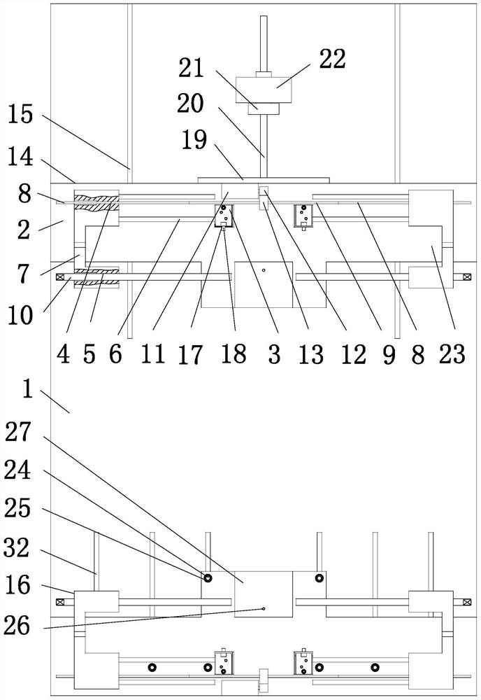
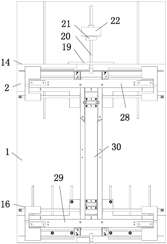
[0018] as attached figure 1 , attached figure 2 Shown: a lower frame body tailor welding tool, including: a base 1, two positioning devices arranged symmetrically; A positioning slider 7 is respectively provided with a positioning screw hole 4 and an adjustment screw hole 5 and is slidably connected to the bottom plate 2 through the transverse guide rail 6, and each end is provided with a screw thread that is adapted to the positioning screw hole 4 and is screwed one by one. The drive shaft 9 of the section 8, the center beam positioning screw 10 screwed one by one with the adjustment screw holes 5, the positioning stepper motor 11 screwed with the bottom plate 2, and the output shaft key connection of the positioning stepper motor 11 The driving gear 12, the driven gear 13 keyed to the driving shaft 9 and meshed with the driving gear 12; the screw threads of the two


PUM


Abstract

The invention relates to a tailor welding tool for a lower frame body, comprising: a base, two positioning devices arranged symmetrically; Screw holes and adjustment screw holes and the positioning slider connected to the bottom plate through the transverse guide rail, each end is provided with a drive shaft that is adapted to the positioning screw hole and one-to-one corresponding to the threaded segment, and two are connected to the adjustment screw hole. A center beam positioning screw corresponding to the screw connection, a positioning stepping motor connected with the bottom plate, a driving gear connected with the output shaft of the positioning stepping motor, a driven gear connected with the driving shaft and meshed with the driving gear; two thread segments The screw threads of the first positioning device are connected with the upper end of the base through longitudinal guide rails; the bottom plate of the second positioning device is detachably connected with the upper end of the base; the first positioning device is equipped with a displacement device.

Description


Claims


Application Information

Patent Timeline
Owner SHUN DA BO NAI TE ELEVATOR
Why Eureka
Try Eureka