Maximizing steam methane reformer combustion efficiency by pre-heating pre-reformed fuel gas
a technology of steam methane reformer and combustion efficiency, which is applied in the direction of gaseous fuel, energy input, separation process, etc., can solve the problems of low value, low efficiency, and inability to disclose detailed implementation, so as to increase the heat content of the fuel gas, increase the thermal efficiency of the smrs, and run more efficiently
- Summary
- Abstract
- Description
- Claims
- Application Information
AI Technical Summary
Benefits of technology
Problems solved by technology
Method used
Image

Examples
second embodiment
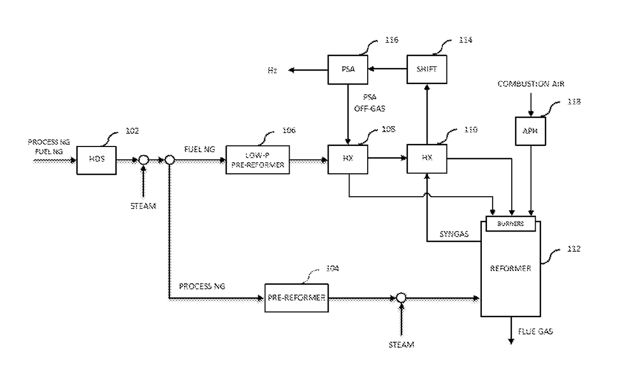
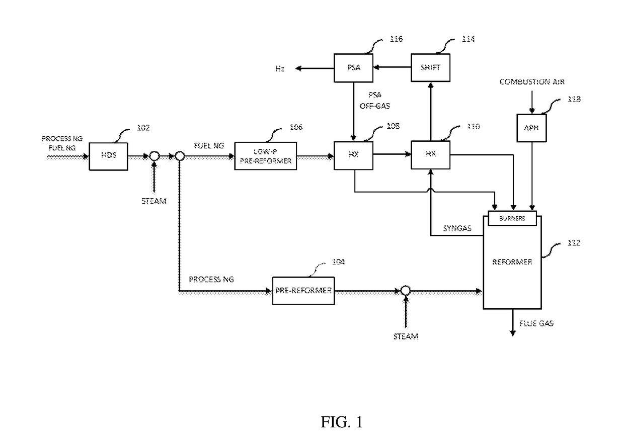
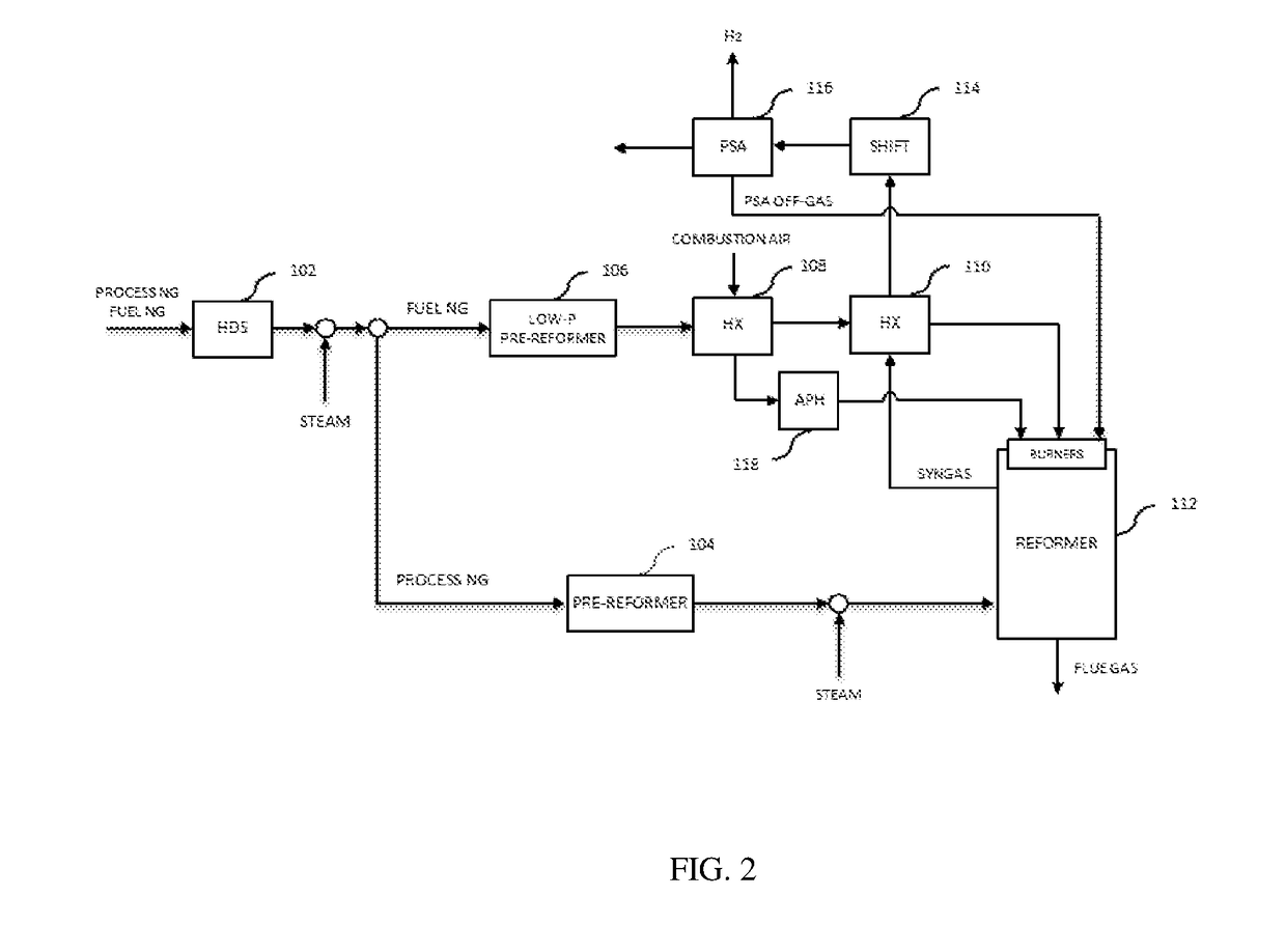
[0062]FIG. 2 illustrates a block flow diagram of an SMR system of the present invention using the cold combustion air stream as the low temperature stream and using the syngas stream as the high temperature stream. The difference between the embodiments illustrated in FIG. 2 and FIG. 1 is the cold combustion air at ambient temperature is used in heat exchanger HX 108 in FIG. 2 to cool down the desulfurized pre-reformed fuel gas stream in order to remove water therein. In this embodiment, the PSA off-gas produced in PSA unit 116 is herein directly sent back to reformer 112 without pre-heating. Alternatively, the PSA off-gas produced in PSA unit 116 may be sent back to reformer 112 pre-heated by a heat exchanger through heat exchange with a waste stream such as a flue gas (not shown). The fuel gas downstream of low-pressure pre-reformer 106 is cooled in heat exchanger HX 108 by heat exchange with the cold combustion air at ambient temperature, down to a temperature below the dew point of
third embodiment
[0063]FIG. 3 illustrates a block flow diagram of an SMR system of the present invention using the hydrocarbons gas (e.g., natural gas) at ambient temperature as the low temperature stream and using the syngas stream as the high temperature stream. The difference between the embodiments illustrated in FIG. 3 and FIG. 2 is the hydrocarbon gas at ambient temperature is used in HX 108 of FIG. 3 to cool the fuel gas stream in order to remove water in the fuel gas, rather than using the cold combustion air.
[0064]In this embodiment, the natural gas for use as process gas and fuel gas is pre-heated by heat exchange with the pre-reformed fuel gas in HX 108. After pre-heated, the natural gas is forwarded to HDS 102 where sulfur in the natural gas is removed. The fuel gas downstream of low-pressure pre-reformer 106 is cooled in HX 108 by heat exchange with the natural gas down to a temperature below the dew point of water to remove water producing a dry fuel gas stream. By cooling the pre-reforme
fourth embodiment
[0065]FIG. 4 illustrates a block flow diagram of an SMR system of the present invention using the PSA off-gas stream as the low temperature stream and the flue gas stream as the high temperature stream. The difference between the embodiments illustrated in FIG. 4 and FIG. 1 is the flue gas stream is used as the high temperature stream in HX 110 of FIG. 4 to heat the dry fuel gas and the syngas is directly sent to shift 114.
PUM
 Abstract
Description
Claims
Application Information
 - R&D Engineer
- R&D Manager
- IP Professional
- Industry Leading Data Capabilities
- Powerful AI technology
- Patent DNA Extraction
Browse by: Latest US Patents, China's latest patents, Technical Efficacy Thesaurus, Application Domain, Technology Topic.
© 2024 PatSnap. All rights reserved.Legal|Privacy policy|Modern Slavery Act Transparency Statement|Sitemap